


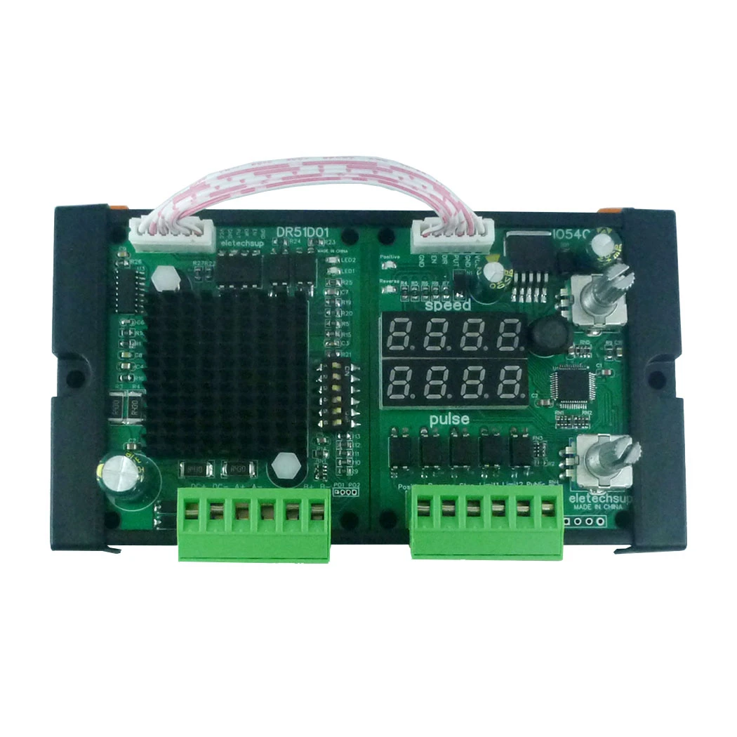
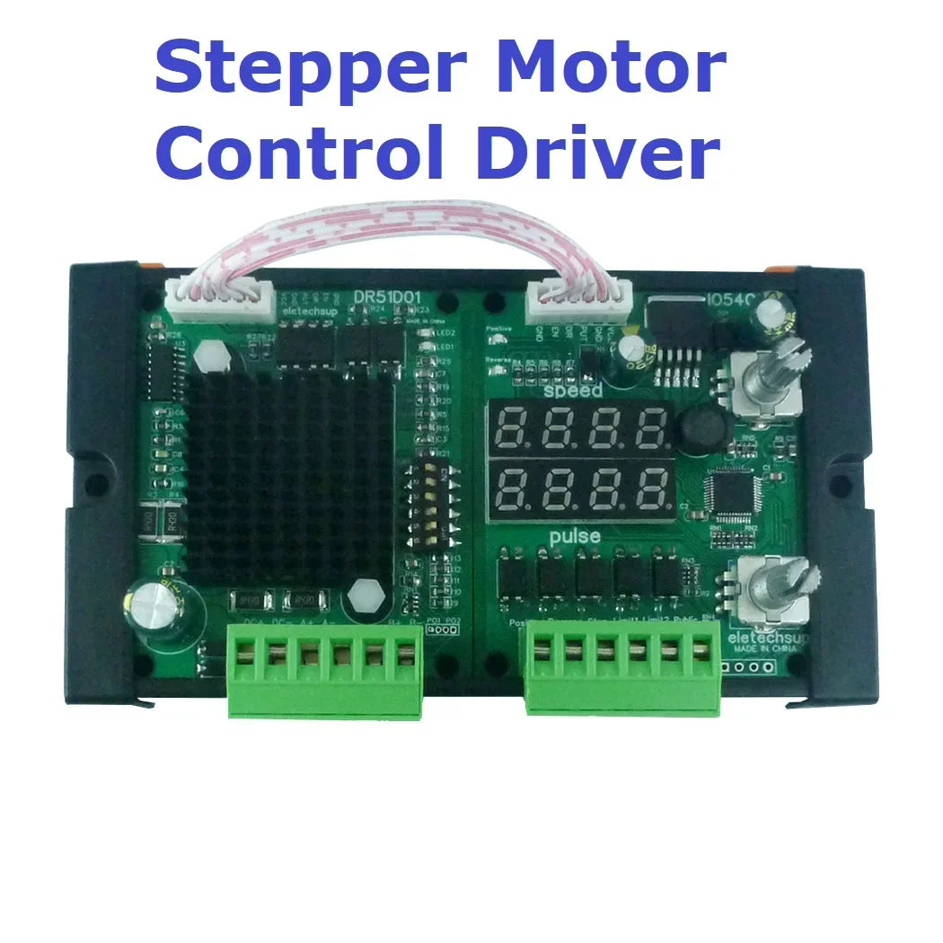
IO54C01 DR51D010-3A Stepper Motor Controller – PWM Pulse Speed Drive Module with Forward/Reverse for 3D Printer CNC Screw Slider Accessories
IO54C01 DR51D010-3A Stepper Motor Controller – PWM Pulse Speed Drive Module with Forward/Reverse for 3D Printer CNC Screw Slider Accessories
Product Name:0-3A 42/57/86 Stepper Motor Forward Reverse Controller PWM Pulse Speed Drive Module For Screw Slider 3D Printer Accessories
Package included:
1 PCS Drive control combination module
OR 1 PCS Stepper motor controller
OR 1 PCS Driver module
Description:
Supply Voltage : DC10V~30V
Drive
Current Range:Within 3A
Controller Type:Uniaxial stepping motor controller
Signal Support:No trigger/NPN (normally open type)
Regulate Way:Ending potentiometer adjustment
Applicable Motor:Within 3A Two-phase step-in motor
Above 3A requires an external drive
Delay Range:0~999.9s
Applicable Drive:Compatible with 99% of the step / servo motor drives on the market
Velocity Range0.1~999.9 Rpm
Impulse Range:1~99990 single pulses
Drive control combination module Weight:170.7g
Drive control combination module Size:138*77*21mm
Stepper motor controller Weight:45.9g
Stepper motor controller Size:71*60*29mm
Driver module Weight:41.5g
Driver module Size:71*60*24mm
(NOTE:The controller does not currently support programmable PLC)
Function: 9 default common functions, can realize the stepping motor point movement, self-locking, limit, angle, pulse, speed, reciprocation cycle, delay control, etc.(Read the functional description for more details)
Note:Please use the switch power supply to power the drive. The power (voltage * current) is too small and it will affect the torque of the motor. The 24V5A or 12V10A universal switch power supply is recommended
Product size chart:


★Short press No. ① potentiometer to enter the function selection mode, select the function and wait for three seconds to automatically save
During the function setting mode, turn the potentiometer No. ② to adjust the intermittent time value of the motor forward and reverse rotation
After setting the function mode, turn the potentiometer No. ① to adjust the motor rotation speed.
★Turn the potentiometer No. ② to adjust the number of pulses: for example, under the condition of 8 subdivision, 1600 pulses are a circle, press one
The lower angle adjustment potentiometer has a decimal point of 160.0 representing 16000 pulses, which is 10 turns.
External drive link mode:
Controller EN Connect Drive EN +
Controller DIR connect to drive DR +
Controller PUL Connect drive PUL +
The controller GND drives DIR-with EN-with PUL-making their negative poles
Description of the working relationship parameters of the stepping motor:
|
Step Angle: Turn the turning angle of the stepping motor. |
|
Guide: one nut distance moved by the stepping motor. |
|
Subdivision: adjust the step angle of stepping motor. |
|
Formula: Step motor 1.8 requires 200 pulses. |
|
Example: when the stepping motor sets 1.8 step angle / 32 subdivision / 8mm guide range, it takes 6,400 pulses to run a circle of 360, and 12,800 pulses when the motor turns 16mm. |
★When the motor is actually used, if the speed requirement is high, and the accuracy and stationarity requirements are not high.For the occasion, you should choose a low subdivision
If the speed is very low, large segmentation should be chosen to ensure smooth, and reduce vibration and noise.
Function Introduction:
|
★P-1:Point motion function Press and hold, turn, and stop with the limit or release. |
|
★P-2:Self-locking function Press positive turn to keep positive turn, press reverse to keep reverse, release constantly touch the limit stop |
|
★P-3:Give the positive signal, the motor is turning, the next positive signal, the motor reverses. |
|
★P-4:Give the positive signal,Encounter limit 1 stop T seconds after automatically reverse to limit 2 stop. |
|
★P-5:The electricity is turning,Encounter limit 1 stop T seconds→Automatic reverse to limit 2 stop T seconds→Automatic positive turn→reverse infinite loop!(General: The motor circulates back and forth between A and B, controlled by the limit) |
|
★P-6:Give forward signal, forward X angle to stop, and reverse signal to reverse X angle to stop. |
|
★P-7:Give the signal of forward rotation, stop by X angle of forward rotation, delay for tincture seconds, and stop by X angle of reverse rotation automatically. |
|
★P-8: Power-on forward rotation X angle stop, delay T seconds → reverse X angle stop, delay T seconds → forward rotation X angle stop. Infinite loop! |
|
★P-9: Give forward signal, stop forward X angle, delay T seconds → Stop forward X angle, infinite loop! Give reverse signal, reverse X angle stop, delay T seconds → reverse X angle stop, endless loop! |
Other Instructions
|
1:About motor:As long as it is a 2-phase 4-wire 5-wire 6-wire 8-wire stepper motor, the current can be controlled within 4A. |
|
2:Can I replace my own drive: It can be replaced as long as there is a similar interface |
|
3:With or without self-locking: all possible; our default delivery is with self-locking function; if self-locking is required; just remove one of the EN+ wires of our controller and leave it unconnected. |
|
4:Regarding the setting of subdivision and current size: our default setting is 8 subdivision; that is, 1600 pulses per circle; the current setting is 0.5A; if it is generally available, try not to adjust it. |
|
Step resolution select function |
|||
|
S1 |
S2 |
S3 |
Function |
|
ON |
ON |
ON |
Standby mode (the OSCM is disabled and the output stage isset to 'OFF'status) |
|
ON |
ON |
OFF |
Full step resolution |
|
ON |
OFF |
ON |
Half step resolution(Type A) |
|
ON |
OFF |
OFF |
Quarter step resolution |
|
OFF |
ON |
ON |
Halfstepresolution(TypeB) |
|
OFF |
ON |
OFF |
1/8stepresolution |
|
OFF |
OFF |
ON |
1/16stepresolution |
|
OFF |
OFF |
OFF |
1/32stepresolution |
|
Current setting |
|||
|
S4 |
S5 |
S6 |
Current value |
|
ON |
ON |
ON |
0.5A |
|
ON |
OFF |
ON |
1A |
|
ON |
ON |
OFF |
1.5A |
|
ON |
OFF |
OFF |
2A |
|
OFF |
ON |
ON |
2.5A |
|
OFF |
OFF |
ON |
3A |
|
OFF |
ON |
OFF |
3.5A |
|
OFF |
OFF |
OFF |
4A |
Common problems and strategies
|
Phenomenon |
Possible problem |
Solution |
|
The Motor does not turn |
The power light does not light up |
Check the power supply circuit, normal power supply |
|
The motor shaft is powerful |
The motor shaft is powerful |
|
|
Subdivision is too small |
Select the right subdivision |
|
|
Is the current set too small |
Select the right current |
|
|
The drive is protected |
On the electricity again |
|
|
The enabling signal is low |
This signal is high or disconnected |
|
|
Do not respond to the control signal |
Not on the electricity |
|
|
Wrong direction of motor |
Wrong connection of motor wire |
Arbitrarily swap the two wires of the same phase of the motor (for example, A+, A- swap wiring positions) |
|
There is an open circuit in the motor wire |
Check and connect |
|
|
The alarm indicator is on |
The motor wire is connected wrong |
Check the wiring |
|
Voltage is too high or too low |
Check the power supply |
|
|
Motor or drive is damaged |
Replace the motor or the drive |
|
|
Location is not allowed |
The signal is disturbed |
Suppress interference |
|
The shielding ground is not connected or unconnected |
Reliable grounding |
|
|
There is an open circuit in the motor wire |
Check and connect |
|
|
Subdivision error |
Set the right subdivision |
|
|
Current is small |
Increase current |
|
|
Stall when the motor is accelerating |
Acceleration time is too short |
Increased acceleration time |
|
Motor torque is too small |
Select high torque motor |
|
|
The voltage is too low or the current is too small |
Increase voltage or current appropriately |
Product features
Product features
Materials and care
Materials and care
Merchandising tips
Merchandising tips


Total items
Product subtotal