


R4PLB04 4DI 4DO RS485 Modbus Remote I/O Core Board – Pulse Counter with 2.54mm Pin Header
R4PLB04 4DI 4DO RS485 Modbus Remote I/O Core Board – Pulse Counter with 2.54mm Pin Header
The R4PLB04 is a multifunctional product:
1. Configurable NPN/PNP level input(Registers 0x00F1)
2. Configurable PNP/NPN level output(Registers 0x00F2)
3. Counts input pulses (registers 0x0020-0x0023)
4. Multiple Output control modes: inching, self-locking, and interlocking
(Registers 0x0000-0x0003)
5. Watchdog function (Register 0x00F3)
6 Remote IO function (Registers 0x00F5-0x00F6)
7 Automatic reporting of digital input(DI) status(Register 0x00F8)
8 Input and output relationship(DI-DO relationship)(Register 0x00FA)
Features:
1: Operating Voltage: DC 3.3-5V(Can be powered by 3.7/3.85V battery)
2: Operating Current: 8-10MA
3: 4ch 3-5V TTL Level NPN Input Ports(Configurable as PNP)
4: 4ch 3-5V TTL Level PNP Output Ports(Configurable as NPN)
5: The input-output relationship can be set to various association modes through instructions(Self-lockingdefault)/Interlocking/Momentary/Interlocking/Output=Input)
6: The input port can remotely control the output port of another board through the RS485 bus
7: The input port has a counting function. It can count pulses greater than 100MS (the pulse width can be set from 10 to 2000MS).
8: Support standard Modbus RTU command, function code, write 05/06/15/16 read 01/02/03
9: With hardware factory reset jumper, shorting the RES jumper for 5 seconds will restore the factory settings.
10: MODBUS commands can be made serial HyperTerminal (serial assistant) OR "Modbus Poll"Enter;
11: Under the MODBUS command mode, it can support up to 254 devices in parallel
12: The default baud rate is 9600BPS. The baud rate can be selected by Conmand 2400 4800 9600 19200 38400 57600 115200BPS
13: The parity can be none parity, even parity and odd parity
14: The data sending and returning time can be set,with a maximum value of 1000ms
15: Size: 17.78*15*2.8MM
16: Weight: 0.8g
Input port
1 Default NPN, can be set to PNP
2 3-5.5V level input
Note: The input port is not isolated, do not over-voltage input
Output port
1 Default PNP, can be set to NPN
2 3.3-5V TTL level output
NOTE:
1 The output level is consistent with the operating voltage
2 The MCU outputs directly, and the load current cannot be greater than 10MA
Precautions for use:
1 The working power supply is DC 3.3-5.5V, no overvoltage and no reverse connection
2 The input port level cannot be greater than 5.5V, otherwise it will cause damage to the port
3 The output port level voltage is consistent with the working voltage, and the output drive current cannot be greater than 5MA
This is a multi-function core board. By configuring registers, you can achieve many useful functions. For details, please see:"R4PLB04 MODBUS RTU Commamd"
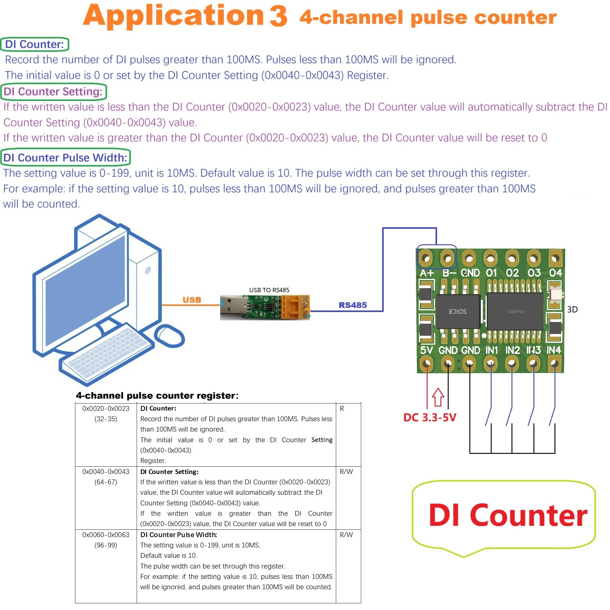
Input port pulse counting function:
DI Counter(registers 0x0020-0x0023):
Record the number of DI pulses greater than 100MS. Pulses less than 100MS will be ignored.
The initial value is 0 or set by the DI Counter Setting (0x0040-0x0043) Register.
DI Counter Setting(registers 0x0040-0x0043):
If the written value is less than the DI Counter (0x0020-0x0023) value, the DI Counter value will automatically subtract the DI Counter Setting (0x0040-0x0043) value.
If the written value is greater than the DI Counter (0x0020-0x0023) value, the DI Counter value will be reset to 0
DI Counter Pulse Width(registers 0x0060-0x0063):
The setting value is 0-199, unit is 10MS. Default value is 10. The pulse width can be set through this register.
For example: if the setting value is 10, pulses less than 100MS will be ignored, and pulses greater than 100MS will be counted.
How to set up remote control:
1The RS485 address and baud rate must be the same (it is recommended to restore both boards to factory settings).
2 Enable Remote IO Receiver: 01 06 00 F6 00 01 A8 38
3 Enable Remote IO Sender : 01 06 00 F5 00 01 58 38

Product features
Product features
Materials and care
Materials and care
Merchandising tips
Merchandising tips


Total items
Product subtotal